
This is a complete guide to configuring and downloading ProSoft MVI69E-MBTCP configuration to the module. The steps are same for all other models of the ProSoft cards.
Common Questions
Is ProSoft Configuration Builder Free?
Yes! Links to download it can be found below.
Does ProSoft device need an EDS file?
Most ProSoft products which either go in a Rockwell PLC rack or communicate over EtherNet/IP (EIP), and therefore most of these products do not require an .EDS file for proper operation.
However, if you do require an EDS file, it can be downloaded from the ProSoft site. Links to downloading it can be found below.
What are the ranges for Read Register Start and Write Register Start in ProSoft Configuration Builder?
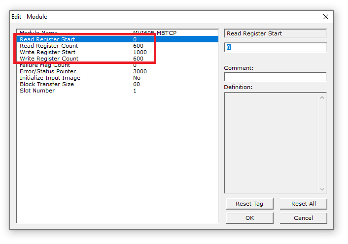
The Read Register Start is the starting register of the module’s Read Data area. While the Write Register Start is the starting register of the module’s Read Data area. These are not a Modbus register address.
The Read Register Start range is 0 to 9999.
The Write Register Start range is 0 to 9999.
The Read Register Count range is 0 to 10000.
The Write Register Count range is 0 to 10000.
You can access it as shown below.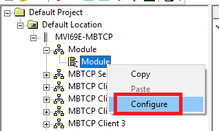
What the ranges for internal address?
An internal address in ProSoft is a software point specific to ProSoft internal database organization. It is a memory location where the data lands in ProSoft after reading or writing to the Modbus devices.
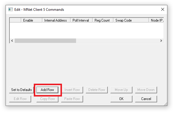
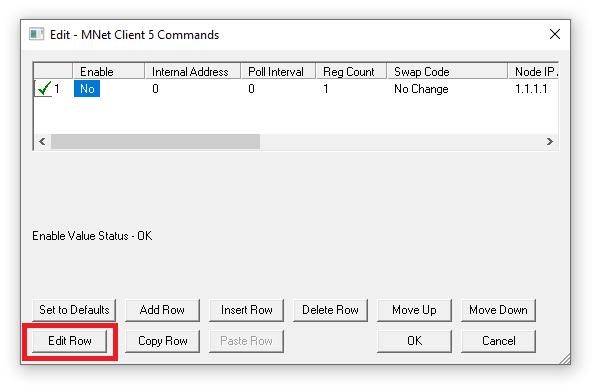
It can be configured by right-clicking on the “MNet Client Command”; as shown below.

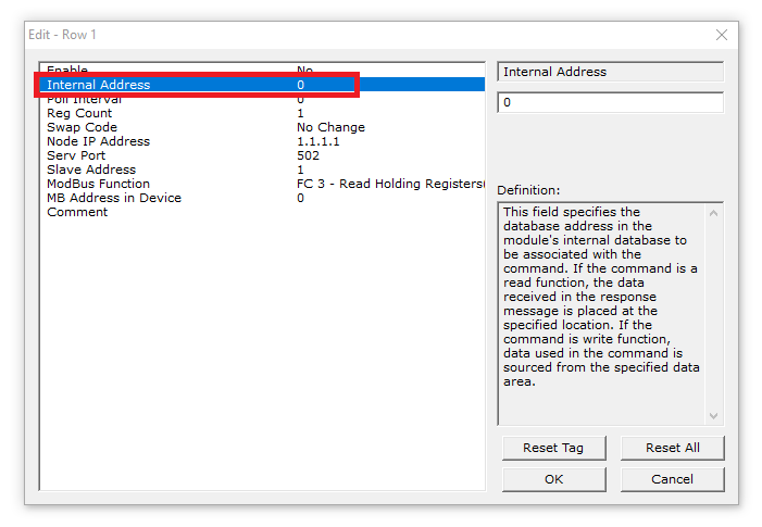
Allowable range is 0 to 65535 for Modbus Function Codes 3, 4, 6, or 16
Allowable range is 0 to 65535 for Modbus Function Codes 1, 2, 5, or 15.
What the maximum ranges Register Count?
This parameter specified the maximum number of registers to poll for one poll.
Modbus Function Codes 5 and 6 ignore this field as they only apply to a single data point.
For word (16 bits), the range is 1 to 125.
For coils (digital), the range is 1 to 800.

What does each of the swap code do?
Swap Code defines how the data should be received from the Modbus devices.
Say for example, if you are polling Modbus registers 40001 and 40002. See screenshot below.
Each Modbus register is a Word (16 bits), and to perform a swap code the driver break the Word into bytes (8 bits). So each Modbus register will have 2 bytes. In our example, the Modbus register 400001 has 2 bytes of A (in red) and B (in green). And lets say we are dealing with a floating point, which requires a 32-bit register (or 2 words or 4 bytes). And if we break the 32-bits into types we have A, B, C and D. See screenshot below.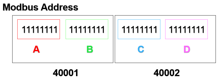
For types of Swap Code, each of the bytes are swapped as follows. See screenshot below.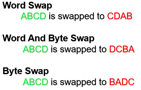
Why do we do this, well that’s just how drivers were programmed way back during the serial communication. For example, Motorola devices receive the MSB (Most Significant Bit) first, while Intel drivers receives the LSB (Least Significant Bit) first.
You can setup the swap code as shown below.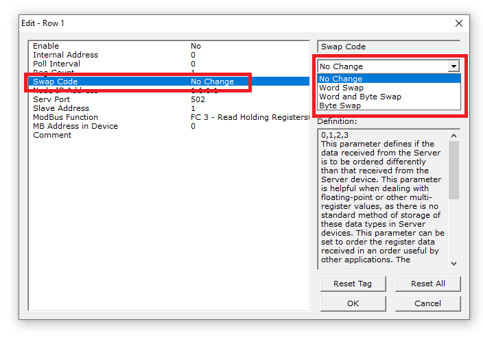
What is the difference between EDS and AOP?
EDS (Electronic Data Sheet) files has information about the hardware, and you can use this file to add the hardware information to your database (such as RSLinx) and allows RSLinx to identify and communicate with the hardware.
AOP (Add-On Profile) contains hardware addressing information and settings for your Ethernet/IP device.
Can I use Generic Module and configure it for ProSoft?
Yes you can but you have to manually set the Connection Parameter (input, output and configuration assembly instance and size) manually, which is specific to the ProSoft card you are using. See screenshot below.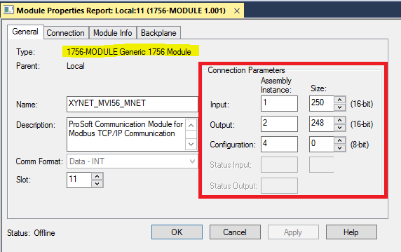
The table below shows what the Connection Parameters should be for MVI56-MNET if you decide to use the 1756-MODULE Generic. The table was extracted from the “MVI56-MNET ControlLogix Platform Modbus TCP/IP Interface Module” (page 21). Link to this document can be found in Reference section.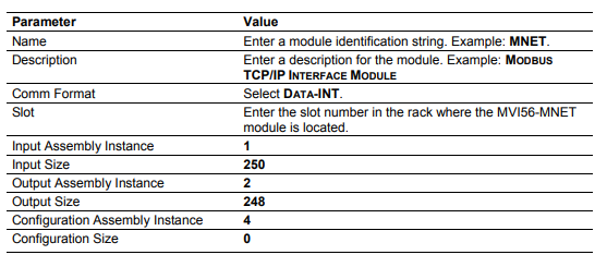
If you want to use the generic module for compact logic to mimic MVI69E-MBTCP, you connection parameter should be set as shown below. The table was extracted from the “MVI69E-MBTCP CompactLogix Platform Modbus TCP/IP Enhanced Communication Module” (page 20). Link to this document can be found in Reference section.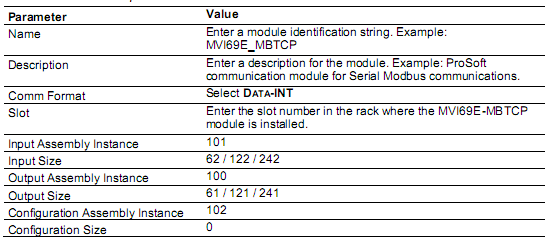
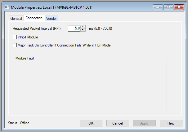
What does the ProSoft Module configuration look like if I were to use hardware specific catalog (EDS and/or AOP installed)?
The screenshot below show what the ProSoft module properties windows looks like for MVI69E-MBTCP. The General tab will vary from ProSoft card models but they are generally all pre-configured.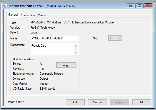
Reference
- MVI69E-MBTCP CompactLogix Platform Modbus TCP/IP Enhanced Communication Module
- Modbus TCP/IP Enhanced Communication Module – EDS File
- Where can I get the proper .EDS file for my module?
- Question about EDS, AOP, Profile
- Prosoft Configuration Builder
- Modbus TCP/IP Enhanced Communication Module – Download EDS and AOP File
- MVI56-MNET ControlLogix Platform Modbus TCP/IP Interface Module
- MVI56E-GSC/GSCXT CompactLogix or MicroLogix Platform – User Manual
- Do you know the difference between EDS files and Add On Profile?