
Learn how to Debug DLOG Error on a SCADAPack Using Telepace Studio.
You are able to store a tabular data in a SCADAPack using a function block called DLOG (Data Logger). This can be programmed using the Schneider-Electric Telepace Studio (programming tool for SCADAPack 357 or any SCADAPack). A DLOG element records entries in a data log when the middle shunt (called “grab data”) transits from off to on.
This tip is not on how to use a DLOG in the Telepace Studio (for Schneider-Electric SCADAPack), but how to resolve DLOG issue. If the DLOG is working, the status register (last integer on the DLOG) should return a value of 10, however if it returns a value of 11, it means that there is already another table already existing in the SCADAPack memory. We will have to delete the DLG memory table and re-create it to resolve this issue. Alternatively, you will have to reset it into a factory setting.
I will demonstrate how to do it on a live system when we do not have that luxury of putting the SCADAPack in to factory reset.
The proceeding sections are directly from the SCADAPack Telepace Studio Help File.
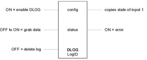
DLOG (Data Logger)
The DLOG element records entries in a data log. When a low to high transition occurs on the enable DLOG input, the data log identified by LogID is created and initialized. If the data log exists and has a different configuration then a status code will be generated. If this occurs, either use a different LogID or delete the log using the delete log input.
While the enable DLOG is ON and a low to high transition occurs on the grab data input, an entry is recorded in the data log identified by LogID.
When the delete log input is low, the records in the data log are deleted.
The top output is a copy of the top input. The error output is ON if creation, configuration or data logging was unsuccessful. The outputs are powered only when the enable input is powered.
Function Block Properties
Configuration Block
Address of the first register (config) of 18 in a sequential block of 4xxxx (holding) registers. These registers contain the information used by the function block. The Element Configuration is used to initially configure the function block. As well, the information in the registers may be changed using other Telepace Studio function blocks or from a Modbus device communicating with the controller.
The block of registers are defined for the function block as follows:
config + 0 = Maximum number of records in the log.
config + 1 = number of data fields.
config + 2 = Field #1 register address
config + 3 = Field #1 data type (see data types below)
config + 4 = Field #2 register address
config + 5 = Field #2 data type
config + 6 = Field #3 register address
config + 7 = Field #3 data type
config + 8 = Field #4 register address
config + 9 = Field #4 data type
config + 10 = Field #5 register address
config + 11 = Field #5 data type
config + 12 = Field #6 register address
config + 13 = Field #6 data type
config + 14 = Field #7 register address
config + 15 = Field #7 data type
config + 16 = Field #8 register address
config + 17 = Field #8 data type
Status Block
Address of the status register. See the Status Codes section below.
Log ID Block
Identifies the internal log. Valid values are 1 to 15.
Status Register
The status register stores the result of a log attempt. It can have the following values. If the status register is not equal to 10 then the error output is turned on.
The log status codes are as follows.
Status Codes Description
10 The configuration is valid and data can be logged.
11 A different configuration already exists for the log.
12 The log ID is invalid or has not been created or RAM battery is too low.
13 The configuration was not valid and was rejected.
14 There is not enough available memory to create a log of the requested size.
15 The number of data fields was invalid.
16 The log was successfully deleted. No log configuration exists.
17 Undefined status
I hope that helps.
Happy programming!!