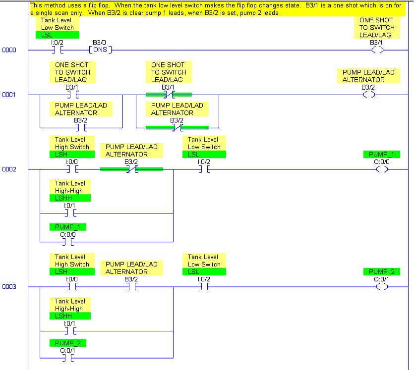
Found a really good reference for lead-lag pump control logic from the PLCTalk.net website. I don’t claim any ownership of this logic.
Basically, this logic controls two pumps to drain fuild out from the tank.
The lead pump will run once a high level condition is met, and the lag pump will follow as soon as a high high level condition is met. The lag pump will stop running when the high high is no longer true, and it will (the lag pump) will shut off as soon as the low condition is met.
To maintain equal run hours, the pumps will be alternating from lead to lag as soon as it is shut off(by the low tank level condition).
Method 1 – Counter Method

Method 2 – Flip Flop Method

More details on Count Up (CTU)
Description
The CTU instruction counts upward over a range of -32,768 to +32,767. Each time the rung goes from false-to-true, the CTU instruction increments the accumulated value by one count. When the accumulated value equals or exceeds the preset value, the CTU sets a done (.DN) bit which your ladder program can use to initiate some action, such as controlling a storage bit or an output device.
CTU instructions are retentive and require an RES instruction to be reset. They will also reset if the counter decrements below the Preset.

Parameters
Counter
Enter a Counter file type (C) address.
Preset
The value that must be reached to set the Done (.DN) bit.
Accum
The current count value.
Status Bits
Examine status bits in the ladder program to trigger an event. The processor changes the states of status bits when the CTU instruction runs. Address status bits by mnemonic.
| This Bit | Is Set When | Is Reset When |
| Count Up Enable Bit .CU (bit 15) | The rung goes true to indicate the instruction has increased its count. Note: during prescan, this bit is set to prevent a false count when the program scan begins. |
|
| Count Up Done Bit .DN (bit 13) | When the accumulated value is greater than or equal to the preset value. |
|
| Count Up Overflow .OV (bit 12) | The up counter has exceeded the upper limit of +32,767 and has wrapped around to –32,768. The CTU counts up from there. |
|
Reference
