Learn how to setup Modbus TCP Master and Slave Barnett ProTalk Link callout system using the Link Configuration Software.
The P1 module is an add-on module to the Barnett ProTalk M1 module, and it provides connectivity between the Barnett ProTalk Link and a PLC.
The P1 module supports the following protocols.
- Modbus slave
- Modbus master
- Modbus TCP/IP slave
- Modbus TCP/IP master
- Allen-Bradley DF1 Point-to-Point PLC5 master
- Allen-Bradley DF1 Point-to-Point SLC-500 master.
As shown in the illustration below, it has the following ports. The illustration below of the ProTalk P1 Module Front Panel is from the “ProTalk Link P2 Configuration Guide”, page 16. Link to this document can be found below in the Reference section.
- RS232
- RS485
- Ethernet

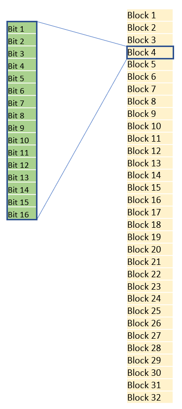
It is stated in the “ProTalk Link P2 Configuration Guide” that “The ProTalk Link can monitor 512 alarms, divided into 32 blocks.”. I do not think this is correct as the first three (3) blocks are reserved for ProTalk system diagnostics. Watch my YouTube channel and I will show you what they are used for. But nevertheless, there are a total of 32 block in the ProTalk Link and each block is an integer (with 16 bits per integer). See screenshot below. Therefore, you can define 512 (3216) discrete alarm points (ON and OFF). But keep in mind that the first 3 blocks are reserved for ProTalk system diagnostics information, which leaves you with 464 (2916) discrete alarm points for you to use for your callout.

Reference
