 This one is going to be a very detail look into the RSLogix500 SLC Status mainly highlighting what each of the register means and how to use it to debug your logic.
I don’t take credit for all these documents as they are straight from the RSLogix500 Help File. I am publishing this just as a reference for all.
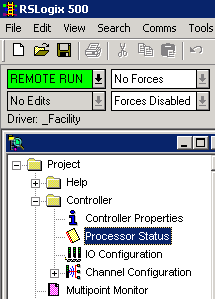
It would be easier to follow if you have a RSLogix500 connected to a PLC. Make sure you are online with the controller if you have that setup. For the rest of us, we can use this article as a Wiki/Dictionary for RSLogix500 SLC Status.
Introduction
In PLC5 and SLC500, data are stored/organised in what they call as Data File. It is basically a way for the PLC to organise its data so that user PLC logic can quickly and efficiently access the data. As an analogy, imagine a drawer with 256 file folders and each file is your data file.
Default data file are created from 0 to 8 when you create a new program (assign process file name).
| Data File Type | File Identifier | File Number |
| Output Status File | O | 0 (zero) |
| Input Status file | I | 1 |
| Process Status File | S | 2 |
| Bit File | B | 3 |
| Timer File | T | 4 |
| Counter File | C | 5 |
| Control File | R | 6 |
| Integer File | N | 7 |
| Floating-Point File | F | 8 |
This article is about Data File 2 (Process Status File). Data File 2 gives you an insight on the status and health of your PLC processor and its operating system / kernel. Here are some key characteristics of Data File 2.
- There must only be ONE Data File 2 per processor.
- Some of the information in the Data File 2 can be modified and some of them are read only.
(1) SLC Status, Main
The status file lets you monitor how your operating system works and lets you direct how you want it to work. Depending on the type of processor you are using all of the fields explained below may not apply.
Fields on this display that are in gray are read-only. Fields shown in white are read/write. However, this information is seldom written to by the user program or programming device (unless you want to reset or clear a function). If you write to status file data, make sure that you first understand the function fully.
This information appears on the Main tab with the Structured Radix selected.
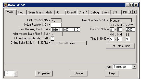
First Pass S:1/15
Can be Yes or No. When the controller sets this bit it indicates that the first scan of the user program is in progress.
Index Register S:24
Enter a value from -32768 to 32767. This word indicates the element offset used in indexed addressing. When an STI, high-speed counter, or Fault Routine interrupts normal execution of your program, the original value of this register is restored when execution resumes.
Free Running Clock S:4
Status
Only the first 8 bits (byte value) of this word are assessed by the processor. This value is zeroed at powerup in the REM Run mode.
You can use any individual bit of this byte in your user program as a 50% duty cycle clock bit. Clock rates for S:4/0 to S:4/7 are: 20, 40, 80, 160, 320, 640, 1280, and 2560 ms.
The application using the bit must be evaluated at a rate more than two times faster than the clock rate of the bit. This is illustrated in the example below for SLC 5/02 and higher processors.
Dynamic Config
All 16 bits of this word are assessed by the processor. The value of this word is zeroed upon power up in the REM Run mode or entry into the REM Run or REM Test mode. It is incremented every 100 microseconds thereafter.
Application note: You can write any value to S:4. It will begin incrementing from this value.
You can use any individual bit of this word in your user program as a 50% duty cycle clock bit. Clock rates for S:4/0 to S:4/15 are:
20, 40, 80, 160, 320, 640, 1280, 2560, 5120, 10240, 20480, 40960, 81920, 163840, 327680, and 655360 ms
The application using the bit must be evaluated at a rate more than two times faster than the clock rate of the bit.
In the following example, bit S:4/3 toggles every 80 ms, producing a 160 ms clock rate. To maintain accuracy of this bit in your application, the instruction using bit S:4/3 (O:1/0 in this case) must be evaluated at least once every 79.999 ms.
Index Across Data Files S:2/3
Can be Yes or No. Double-click within this field to enable a list box allowing you to select Yes to index anywhere from data file B3:0 to the end of the last declared data file. The SLC 5/03 and SLC 5/04 allow you to index from O0:0 to the last data file.
CIF Addressing Mode S:2/8
This bit controls the mode used by the controller to address elements in the CIF file (Communication Interface File) (data file 9) when processing a communication request. When 0, word address mode is enabled; when 1 byte address mode is enabled.
Online Edits S:33/11-S:33/12
Double-click within this field to enable a list box allowing you to select from: No online edits exist, Online edits are disabled, Testing online edits, or Undefined state. Examine the state of these bits with your user program to count the number of online edit sessions, flag an alarm, or place your application in a special state designed for online edit sessions.
Day of the Week
Contains the day of the week as indicated by the computer. You can synchronize this setting with the setting contained on the controller by clicking Set Date and Time.
Date S:39-37
Contains the date of the calendar. To disable, write zeros to all fields. You can synchronize this setting with the setting contained on the controller by clicking Set Date and Time.
Time S:40-42
Contains the time value of the clock. To disable, write zeros to all fields. You can synchronize this setting with the setting contained on the controller by clicking Set Date and Time.
Set Date & Time
(5/03, 5/04, and 5/05 only) Click this button when online to synchronize the date/time of the controller with the computer’s current date and time. Will also synchronize the day of the week when using the 5/05 controller.
(2) SLC Status, Processor
The status file lets you monitor how your operating system works and lets you direct how you want it to work. Depending on the type of processor you are using all of the fields explained below may not apply.
Fields on this display that are in gray are read-only. Fields shown in white are read/write. However, this information is seldom written to by the user program or programming device (unless you want to reset or clear a function). If you write to status file data, make sure that you first understand the function fully.
This information appears on the (Proc)essor tab with the Structured Radix selected.
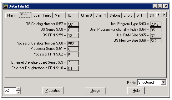
OS Catalog Number S:57
This is the operating system catalog number. For example, the value of 400 indicates operating system -OS400.
OS Series S:58
This is the operating system series. The value of 0 indicates series A and the value of 1 indicates series B, etc.
OS FRN S:59
This is the operating system firmware release number. The value of 1 indicates FRN1 and the value of 2 indicates FRN2, etc.
Processor Catalog Number S:60
This is the catalog number of the processor. For example, the value of 532 indicates -L532 and the value of 534 indicates -L534.
Processor Series S:61
This is the processor series. The value of 0 indicates series A and the value of 1 indicates series B, etc.
Processor FRN S:62
This is the processor revision. The value of 1 indicates REV1 and the value of 2 indicates REV2, etc.
User Program Type S:63
This is the numeric code for the programming device that created the user program.
User Program Functionality Index S:64
This is the numeric code for the level of functionality contained in a given program type.
User RAM Size S:65
This is the size of NVRAM (non-volatile memory) in 16 bit K words. for example, the value of 64 equals 64K words of NVRAM. NVRAM holds its content without power.
OS Memory Size S:66
This is the size of flash EEPROM operating system memory in 16 bit K words. for example, the value of 128 equals 128K words of memory. Flash EEPROM is a memory chip that holds its content without power, but must be erased in bulk.
Ethernet Daughterboard Series S:9
(For 5/05 Ethernet controllers only) The series number of the communication circuit board in the 5/05 processor that facilitates Ethernet communications.
Ethernet Daughterboard FRN S:10
(For 5/05 Ethernet controllers only) The firmware revision number of the communication circuit board in the 5/05 processor that facilitates Ethernet communications.
(3) SLC Status, Scan Times
The status file lets you monitor how your operating system works and lets you direct how you want it to work. Depending on the type of processor you are using all of the fields explained below may not apply.
Fields on this display that are in gray are read-only. Fields shown in white are read/write. However, this information is seldom written to by the user program or programming device (unless you want to reset or clear a function). If you write to status file data, make sure that you first understand the function fully.
This information appears on the Scan Times tab with the Structured Radix selected.
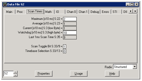
Maximum S:22
This word indicates the maximum observed interval between consecutive program cycles. The value (expressed in 10 ms increments when S:33/13=0, or in 1ms increments when S:33/13=1) is the time elapsed in the longest program cycle of the controller. The I/O scan, processor overhead, and communication servicing is not included in this measurement.
Average S:23
This word indicates a weighted running average time. The value (expressed in 10 ms increments when S:33/13=0, or in 1ms increments when S:33/13=1) indicates the time elapsed in the average program cycle of the processor. The I/O scan, processor overhead, and communication servicing is not included in this measurement.
Current [x10 ms] S:3L
The value of this byte (low byte) tells you how much time elapses in a program cycle. When SVC or REF instructions are contained in your program, this value will appear to be erratic when you monitor it with a programming device. This is because the SVC or REF instructions allow this value to be read in mid-scan, while it is still incrementing.
Watchdog [x10 ms] S:3H
This byte value (high byte) contains the number of 10 ms ticks allowed to occur during a program cycle. The default value is 10 (100 ms), but you can increase this to 250 (2.5 seconds) or decrease it to 0, as your application requires. If the program scan value (S:3L) equals the watchdog value, a watchdog major error is declared (code 0022).
Last 1ms Scan Time S:35
This value tells you how much time elapsed in a program cycle. This word value is only updated by the processor once each scan, immediately preceding the execution of rung 0 – file 2, or upon return of a REF (I/O Refresh) instruction.
Scan Toggle Bit S:33/9
This bit changes state each and every execution of an END, TND, or REF instruction. It is always cleared when entering RUN mode. Use this bit in your user program for applications such as multiplexing subroutine execution.
Timebase Selection S:33/13
This bit determines the timebase used to average the Scan time (S:23) and the maximum Scan Time (S:22). When clear, the value contained in the average and maximum scan times represent the number of 10 ms increments that have occurred. When set, the value contained in the average and maximum scan times represent the number of 1 ms increments that have occurred. This value is clear by default (10 ms timebase).
(4) SLC Status, Math
The status file lets you monitor how your operating system works and lets you direct how you want it to work. Depending on the type of processor you are using all of the fields explained below may not apply.
Fields on this display that are in gray are read-only. Fields shown in white are read/write. If you write to status file data, make sure that you first understand the function fully.
This information appears on the Math tab with the Structured Radix selected.
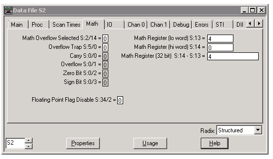
Math Overflow Selected S:2/14
Set this bit to 1 when you intend to use 32-bit addition and subtraction.
When this bit is set and the result of an ADD, SUB, MUL, or DIV instruction cannot be represented in the destination address (underflow or overflow): the overflow bit is set S:0/1, the overflow trap bit is set S:5/0, and the destination address contains the unsigned truncated least significant 16 bits of the result.
When this bit is reset (default) and the result of an ADD, SUB, MUL, or DIV instruction cannot be represented in the destination address (underflow or overflow): the overflow bit is set S:0/1, the overflow trap bit is set S:5/0, and the destination address contains 32767 if the result is positive or -32768 if the result is negative.
Overflow Trap S:5/0
When this bit is set (1) by the controller, it indicates that a mathematical overflow has occurred in the ladder program.
Carry S:0/0
This bit is set (1) by the controller if a mathematical carry or borrow is generated. Otherwise the bit remains cleared.
Overflow S:0/1
This bit is set (1) by the controller when the result of a mathematical operation does not fit in its destination. Otherwise the bit remains cleared.
Zero Bit S:0/2
This bit is set (1) by the controller when the result of math or data handling instructions is zero.
Sign Bit S:0/3
This bit is set (1) by the controller when the result of math or data handling instructions is negative.
Floating Point Flag Disable S:34/2
When set to (1) this bit disables the processing of math flags when using floating point math. When this bit is clear (0) math flags are processed. Math flags affect the ADD, SUB, MUL, DIV, NEG, SQR, and MOV instructions, so when this bit is set, the execution time for these instructions is reduced.
Math Register (low word) S:13
See Math Register (32 Bit) below.
Math Register (high word) S:14
See Math Register (32 Bit) below.
Math Register (32 bit ) S:14-S:13
Use this double register to produce 32-bit signed divide and multiply operations, precision divide or double divide operations, and 5-digit BCD conversions. These two words are used in conjunction with the MUL, DIV, DDV, FRD, and TOD math instruction. The math register value is assessed upon execution of the instruction and remains valid until the next MUL, DIV, DDV, FRD, or TOD instruction is executed in the user program.
(5) SLC Status, I/O
The status file lets you monitor how your operating system works and lets you direct how you want it to work. Depending on the type of processor you are using all of the fields explained below may not apply.
Fields on this display that are in gray are read-only. Fields shown in white are read/write. If you write to status file data, make sure that you first understand the function fully. (Refer to your Instruction Set Reference Manual for an explanation of the data contents of the status file.)
This information appears on the I/O tab with the Structured Radix selected.
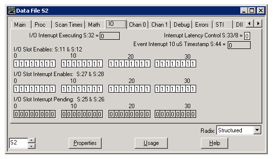
I/O Interrupt Executing S:32
This word indicates the slot number of the specialty I/O module that generated the currently executing Interrupt Subroutine (ISR). This value is cleared upon completion of the ISR, at REM Run mode entry, or on power up.
Interrupt Latency Control S:33/8
When set (1) you are guaranteed to be at rung 0 of your interrupt subroutine within the interrupt latency period when an interrupt occurs.
Latency is the period of time between your I/O module’s request for an interrupt and the actual start of the interrupt subroutine. The latency period differs from processor to processor.
Event Interrupt 10 us Timestamp S:44
This value measures the amount of time that expires between consecutive interrupt subroutine executions (in increments of 10 microseconds).
I/O Slot Enables: S:11 and S:12
These two words are bit-mapped to represent the 30 possible I/O slots in an SLC 500 system. Slot 0 corresponds to S:11/0; it is used to represent slot 0 for fixed I/O systems. Slots 1-30 correspond to S:11/1 through S:12/14.
When any bit is set (1) (default condition), the I/O module in the referenced slot is updated in the I/O scan of the processor operating cycle.
When any bit is cleared (0), the I/O module in the referenced slot is ignored (frozen at its last value). This condition persists until power is removed, the REM Run mode is exited, or a major fault occurs.
I/O Slot Interrupt Enables S:27 and S:28
Slots 1-30 correspond to bits S:27/1 through S:28/14 and must be set (1) when an interrupt occurs to allow the interrupt subroutine to execute. The default value of each bit is 1.
I/O Slot Interrupt Pending S:25 and S:26
Slots 1-30 correspond to bits S:25/1 through S:26/14. These bits are set (1) when their corresponding I/O Slot Interrupt Enable bit is clear at the time of an interrupt request. These bits are cleared (0) when their corresponding I/O Slot Interrupt Enable bit is set, or when an associated RPI (Reset Pending I/O Interrupt) instruction is executed.
(6) SLC Status, Chan 0
The status file lets you monitor how your operating system works and lets you direct how you want it to work. Depending on the type of processor you are using all of the fields explained below may not apply.
Fields on this display that are in gray are read-only. Fields shown in white are read/write. However, this information is seldom written to by the user program or programming device (unless you want to reset or clear a function). If you write to status file data, make sure that you first understand the function fully.
This information appears on the Chan 0 tab with the Structured Radix selected.
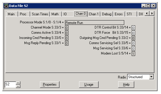
Processor Mode S:1/0-S:1/4
This indicates the controller mode status. Default = Remote program mode. (Available with SLC 5/03, 5/04 and 5/05.)
Channel Mode S:33/3
When clear (0), the channel 0 communication port is in the User mode (ASCII mode). When set (1), channel 0 is in the System mode (DF1 mode). Make this selection on the Channel Configuration dialog box. To access this dialog box double-click on Channel Configuration in the project tree. (Available with SLC 5/03, 5/04 and 5/05.)
Comms Active
This bit is set (1) by the controller when the controller receives valid data from its RS-232 channel. If the controller does not receive valid data for 10 seconds through this channel, the bit is cleared (0). (Status bit S:33/3 with SLC 5/03, 5/04, and 5/05 and status bit S:1/7 with SLC 5/01 and 5/02.)
Incoming Cmd Pending
When set (1), the processor detected that another node on the channel 0 network requested information or supplied a command to it. When cleared (0), the processor serviced the request or command. Use this bit as a condition of an SVC instruction to enhance the communication capability of your processor. (Status bit S:33/0 with SLC 5/03, 5/04 and 5/05, and Status bit S:2/5 with SLC 5/02.)
MSG Reply Pending
This is set (1), when another node on the channel 0 network supplied the information that you requested in the MSG instruction of your processor. This bit is clear (0) when the processor stores the information and updates your MSG instruction. (Status bit S:33/1 with SLC 5/03, 5/04 and 5/05, and Status bit S:2/6 with SLC 5/02.)
Use this bit as a condition of an SVC instruction to enhance the communication capability of your processor.
DH485 Pass-Thru Disable Bit S:34/0
The default setting for this bit is clear (0). When clear (0) the processor allows packets to be passed from one channel to the other. When set (1) this pass-thru is not allowed. Channel 0 must be configured for DH-485 protocol. Only packets that contain the Internet network layer and whose Destination Link ID equals that specified for the opposite channel will be passed. The default Link ID for channel 0 is (1). The default Link ID for channel 1 is (2).
DF1 Pass-Thru Enable Bit S:34/5
The default setting for this bit is clear (0). When this bit is set, pass-thru operation is enabled between Channel 0 and Channel 1. Channel 0 must be configured for DF1 Full-duplex protocol.
DF1 Pass-Thru Remote/Local S:34/6
This bit is used to determine whether DF1 commands coming into channel 0 should be passed thru on channel 1 as remote DH-485 packets or as local DH-485 packets. When set ( 1 ) the commands are passed thru as Local packets. When reset ( 0 ) the commands are passed thru as Remote packets. SLC 500 fixed, 5/01, and 5/02, as well as all variations of ControlLogix, FlexLogix, and CompactLogix controllers, will only respond to local DH-485 packets, while DH-485 PanelView downloads will only work with remote DH-485 packets. SLC and MicroLogix work fine in all cases with either setting. If local mode is selected, a queue is set up that holds up to 30 passthru commands waiting for replies from active nodes. If replies don’t make it back for any reason (such as noise on the network), then slots in the queue could potentially be lost until the next power cycle. Channel 0 must be configured for DF1 and the previous bit (DF1 Pass Thru Enable bit S:34/5) must be set ( 1 ).
DF1 Pass-Thru Local Cmd Queue Full S:34/7
(Read-only). If this bit is set ( 1 ) it indicates that the pass-thru local command queue is full.
The Local Passthru Queue can be flushed at any time by executing the ACL instruction with the Receive Buffer set to No and the Transmit Buffer set to Yes.
As the Local Passthru Queue approaches being full, S:34/7 may toggle between 0 and 1. To verify that the Local Passthru Queue is completely full, use the Local Passthru Queue Full bit as a pre-condition to a timer (TON) with a preset of ten seconds or longer. Then use the timer done bit as a pre-condition for executing the ACL instruction.
DTR Control Bit S:33/14
(Valid with SLC 5/03, 5/04 and 5/05.) When this bit is set (1) you can perform DTR (Data Terminal Ready) dialing by writing to S:33/15. When this bit is cleared (0) the channel 0 DTR signal (pin 4) is controlled by the standard communication driver.
When channel 0 is configured for DH-485, S:33/14 must be clear for proper operation.
DTR Force Bit S:33/15
(Valid with SLC 5/03, 5/04 and 5/05.) The high/low state indicated by this bit is used by the DTR (Data Terminal Ready) control bit (S:33/14) when that bit is set. When this bit is set (and S:33/14 is also set) the DTR pin is forced high. When this bit is cleared (and S:33/14 is also set) the DTR pin is forced low.
Outgoing MSG Cmd Pending
This bit is set (1) when one or more channel 0 messages in your program are enabled and waiting, but no message is being transmitted at the time. As soon as transmission of a message begins, the bit is cleared. (Status bit S:33/2 with SLC 5/03, 5/04 and 5/05, and Status bit S:2/7 with SLC 5/02.)
Comms Servicing Sel
When set (1), only one channel 0 communication request/command will be serviced per END, TND, REF, or SVC instruction. When clear, all serviceable incoming or outgoing communication requests/commands will be serviced per END, TND, REF, or SVC instruction.
When clear, your communication throughput will increase. Your scan time will also increase if several communication commands/requests are received in the same scan. (Status bit S:33/5 with SLC 5/03, 5/04 and 5/05, and Status bit S:2/15 with SLC 5/02.)
MSG Servicing Sel S:33/6
(Valid with SLC 5/03, 5/04 and 5/05.) This bit is only valid when the channel 0 Comms Servicing Selection (S:33/5) is clear (which selects service all commands). When S:33/6 is set and S:33/5 is clear, all outgoing channel 0 MSG instructions will be serviced per END, TND, SVC, or REF instruction. Otherwise, only one outgoing channel 0 MSG command or reply will be serviced per END, TND, SVC, or REF instruction.
Modem Lost S:5/14
(Valid with SLC 5/03, 5/04 and 5/05.) This bit is set (1) when communication channel 0 is in the System mode, configured for Modem communication, and cannot communicate with the modem. Otherwise this bit is cleared. The modem is considered to be lost when Carrier Detect (CD) is inactive for more than 10 seconds or if Data Set Ready (DSR) becomes inactive. CD and DSR are pins of DF1 Channel 0. If Control Line = NO HANDSHAKING this bit is always set (1).
(7) Channel 1 (Ethernet) Status
The status file lets you monitor how your operating system works and lets you direct how you want it to work. Depending on the type of processor you are using all of the fields explained below may not apply.
Fields on this display that are in gray are read-only. Fields shown in white are read/write. If you write to status file data, make sure that you first understand the function fully.
This information appears on the Chan 1 tab with the Structured Radix selected. For more specific information about the messaging, collisions, or errors that occurred on the channel refer to the Ethernet, channel 1, general operating status dialog box.
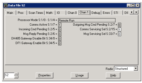
Processor Mode S:1/0-S:1/4
Default = Remote program mode. This may be any of the following: Remote Download in Progress, Remote Program Mode, Suspend Idle, Remote Run, Remote Test Continuous, or Remote Test Single Scan.
Comms Active S:1/7
This bit is set (1) by the controller when the controller receives valid data from its RS-232 channel. If the controller does not receive valid data for 10 seconds through this channel, the bit is cleared (0).
Incoming Cmd Pending S:2/5
When set (1), the processor detected that another node on the channel 0 network requested information or supplied a command to it. When cleared (0), the processor serviced the request or command. Use this bit as a condition of an SVC instruction to enhance the communication capability of your processor.
MSG Reply Pending S:2/6
This is set (1), when another node on the channel 0 network supplied the information that you requested in the MSG instruction of your processor. This bit is clear (0) when the processor stores the information and updates your MSG instruction.
Use this bit as a condition of an SVC instruction to enhance the communication capability of your processor.
Outgoing MSG Cmd Pending S:2/7
When set, one or more messages in your program are enabled and waiting, but no message is being transmitted at the time. This bit is cleared as soon as transmission of a message begins. Use this bit as a condition for an SVC instruction to enhance the communication capability of your processor.
Comms Servicing Selection S:2/15
When set, only one communication request/command can be serviced per END, TND, REF, or SVC. When clear, all serviceable incoming or outgoing communication requests/commands can be serviced per END, TND, REF, or SVC. When clear, your communication throughput will increase. However, your scan time will increase if several communication requests/commands are received on the same scan.
To prevent inadvertent changes to this setting, program an unconditional OTL instruction at address S:2/15 to ensure one request/command operation, or program an unconditional OTU instruction at address S:2/15 to ensure multiple request/command operations.
MSG Servicing Selection S:33/7
This bit is only valid when the channel 1 Comms Servicing Selection bit (S:2/15) is clear (which selects service all commands). When S:33/7 is clear and S:2/15 is clear, all outgoing channel 1 MSG instructions are serviced per END, TND, SVC, or REF instruction. Otherwise, only one outgoing channel 1 MSG command or reply is serviced per END, TND, SVC, or REF instruction.
(8) SLC Status, Debug
The status file lets you monitor how your operating system works and lets you direct how you want it to work. Depending on the type of processor you are using all of the fields explained below may not apply.
Fields on this display that are in gray are read-only. Fields shown in white are read/write. However, this information is seldom written to by the user program or programming device (unless you want to reset or clear a function). If you write to status file data, make sure that you first understand the function fully.
This information appears on the Debug tab with the Structured Radix selected.
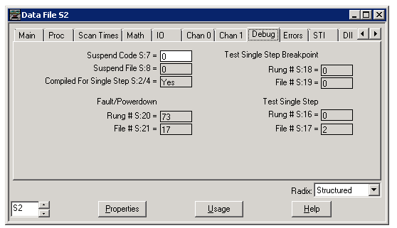
Suspend Code S:7
When a non-zero value appears in S:7, it indicates that the SUS instruction identified by this value has been evaluated as true, and the Suspend Idle mode is in effect. This pinpoints the conditions in the application that caused the Suspend Idle mode. This value is not cleared by the processor.
Suspend File S:8
This word contains the program file number in which a true SUS instruction is located. This value is not cleared by the processor.
Compiled For Single Step S:2/4
When clear, the Single Step Test mode function is not available. Clear (0) also indicates that debug registers S:16 through S:21 are inoperative. When set, the program can operate in the Single Step Test mode.
Fault/Powerdown:
Rung # S:20 – File # S:21
This is the rung and file number that the processor last executed before a major error or powerdown occurred.
Test Single Step Breakpoint:
Rung # S:18 – File # S:19
This is the rung and file number that the processor should stop in front of when executing in the Test Single Step mode. If both rung and file # are 0, the processor will step to the next rung only, otherwise the processor will continue until it finds a rung/file equaling the values indicated in these fields. This feature is built in to the SLC 5/03 and SLC 5/04 processors.
Test Single Step:
Rung # S:16 – File # S:17
This is the rung and file number that the processor will execute next when operating in the Test Single Step mode. This feature is built in to the SLC 5/03 and SLC 5/04 processors.
(9) SLC Status, Error
The status file lets you monitor how your operating system works and lets you direct how you want it to work. Depending on the type of processor you are using, all of the fields explained below may not apply.
Fields on this display that are in gray are read-only. Fields shown in white are read/write. However, this information is seldom written to by the user program or programming device (unless you want to reset or clear a function). If you write to status file data, make sure that you first understand the function fully.
This information appears on the Error tab with the Structured Radix selected.
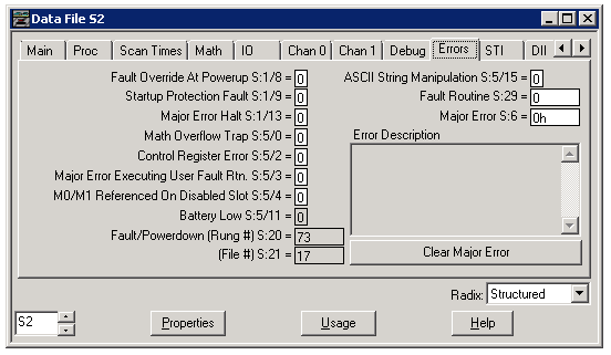
Fault Override at Powerup S:1/8
When set, this bit causes the controller to clear the Major Error Halted bit S:1/13 and Minor error bits S:5/0 to S:5/7 on power up if the processor had previously been in the REM Run mode and had faulted. The controller than attempts to enter the REM Run mode. Set this bit offline only.
Startup Protection Fault S:1/9
When this bit is set and power is cycled while the controller is in the REM Run mode, the controller executes the user fault routine prior to the execution of the first scan of your program.
Major Error Halt S:1/13
This bit is set by the controller any time a major error is encountered. If a major fault state exists, you must correct the condition causing the fault, and then clear the fault.
Math Overflow Selected S:5/0
When this bit is set by the controller, it indicates that a mathematical overflow has occurred in the ladder program.
Control Register Error S:5/2
The LFU, LFL, FFU, FFL, BSL, BSR, SQO, SQC and SQL instructions are capable of generating this error. If this bit is set, the error bit of a control word used by the instruction has been set.
Major Error (Executing User Fault Rtn.) S:5/3
This bit is set if while processing a fault routine (due to a major error) another major error occurs.
M0/M1 Referenced On Disable Slot S:5/4
This bit is set whenever any instruction references an M0 or M1 module file element for a slot that is disabled (via its I/O slot enable bit). When set (1), an instruction could not execute properly due to the unavailability of the addressed M0 or M1 data.
If this bit is ever set when an END, TND, or REF instruction executes, a major error (0020) is declared. To avoid this type of major error from occurring, examine the state of this bit following a M0-M1 referenced instruction, take appropriate action, and then clear this bit using an OTU instruction or a CLR instruction.
Battery Low S:5/11
This bit is set whenever the Battery Low LED in on. This bit is cleared when the Battery Low LED is off. It is updated only in the REM Run or REM Test modes.
Fault/Powerdown (Rung #) S:20 – (File #) S:21
This is the word and file that the processor last executed before a major error or powerdown occurred.
ASCII String Manipulation S:5/15
This bit is set (1) when an attempt is made to process a string using an ASCII instruction that exceeds 82 characters in length.
Fault Routine S:29
You enter a program file number (3-255) to be used in all recoverable and non-recoverable major errors. Program the ladder logic of your fault routine in the file you specify. Write a 0 value to disable the routine.
Major Error S:6
A hexadecimal code is entered in this word by the controller when a major error is declared. This word is not cleared by the controller. Click here for an explanation of the error codes that might display.
Last Major Error (Applies to SLC 5/03, 5/04 and 5/05 series C processors only)
This enhancement allows for a second level of debugging. The last major fault code is stored here. It is NOT cleared by cycling the processor from program to run. It allows you to peek into this data location while the system is up and running and observe the fault code for purposes of analysis and debugging. Also, when the startup protection fault routine is run, S:54 preserves the error code, allowing you to see the code that may have caused the startup protection fault routine to execute.
Error Description
A read-only description of the error is provided here.
Clear Major Error
Click this button to clear any indication of a major fault. Always make sure that the condition that resulted in the error has been corrected first.
(10) SLC Status, STI
The status file lets you monitor how your operating system works and lets you direct how you want it to work. Depending on the type of processor you are using all of the fields explained below may not apply.
Fields on this display that are in gray are read-only. Fields shown in white are read/write. However, this information is seldom written to by the user program or programming device (unless you want to reset or clear a function). If you write to status file data, make sure that you first understand the function fully.
This information appears on the STI tab with the Structured Radix selected.
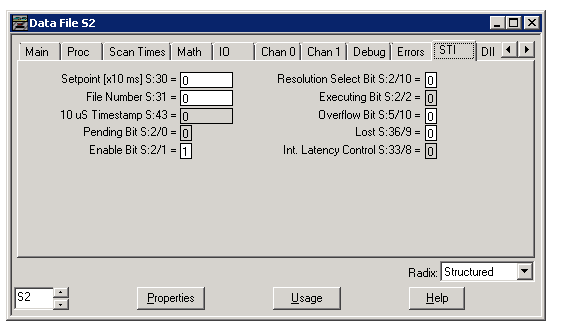
Setpoint S:30
Enter the timebase to be used in the STI. The time can range from 10 to 2550 ms. (This value is expressed in 10 ms increments when S:2/10=0, or in 1ms increments when S:2/10=1) Enter a 0 to disable the STI.
File Number S:31
You enter a program file number (3-255) to be used as the selectable timed interrupt subroutine. Write a 0 value to disable the STI.
10 us Timestamp S:43
This value is used to measure the amount of time that expires between consecutive interrupt subroutine executions (in increments of 10 microseconds). This value is updated upon each entry into the interrupt subroutine.
Pending Bit S:2/0
When set, this bit indicates that the STI timer has timed out and the STI routine is waiting to be executed. This bit is cleared upon starting the STI routine, ladder program, exit of the REM Run or Test mode, or execution of a true STS instruction.
Enable Bit S:2/1
This bit may be set or reset using the STS, STE, or STD instruction. If set, it allows execution of the STI if the STI setpoint S:30 is non-zero. If clear, when an interrupt occurs, the STI subroutine does not execute and the STI Pending bit is set. The STI Timer continues to run when this bit is disabled. The STD instruction clears this bit.
Resolution Select Bit S:2/10
When his bit is cleared (0) uses a 10 ms timebase for the STI Setpoint value.
Executing Bit S:2/2
When set, this bit indicates that the STI timer has timed out and the STI subroutine is currently being executed. This bit is cleared upon completion of the STI routine, ladder program, or REM Run or Test mode.
Overflow Bit S:5/10
This bit is set whenever the STI timer expires while the STI routine is either executing or disabled and the pending bit is already set.
Lost S:36/9
This bit is set whenever the STI timer expires while the STI routine is either executing or disabled and the pending bit is already set.
Int Latency Control S:33/8 – Interrupt Latency Control S:33/8
When set (1) you are guaranteed to be at rung 0 of your interrupt subroutine within the interrupt latency period when an interrupt occurs.
Latency is the period of time between your I/O module’s request for an interrupt and the actual start of the interrupt subroutine. The latency period differs from processor to processor.
(11) SLC Status, DII
The status file lets you monitor how your operating system works and lets you direct how you want it to work. Depending on the type of processor you are using all of the fields explained below may not apply.
Fields on this display that are in gray are read-only. Fields shown in white are read/write. However, this information is seldom written to by the user program or programming device (unless you want to reset or clear a function). If you write to status file data, make sure that you first understand the function fully.
This information appears on the DII tab with the Structured Radix selected.
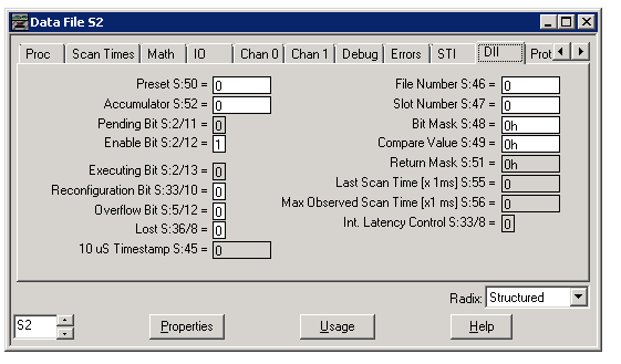
Preset S:50
When this value is equal to 0 or 1, an interrupt is generated each time the bit transitions specific words in S:48 and S:49. When this value is between 2 and 32767, a count occurs each time the bit transition comparison cycle is satisfied. An interrupt is generated when the preset value reaches 1. This bit is applied upon detection of a DII Reconfigure bit, each DII ISR exit, and at each end of scan (END, TND, or REF).
To provide protection from inadvertent data monitor alteration of your selection, program an unconditional MOV instruction containing the preset value of your DII to S:50.
Accumulator S:52
The DII accumulator contains the number of down count transitions that have occurred (see S:50). When a count occurs, and the accumulator is greater than or equal to the preset value, a DII interrupt is generated.
Pending Bit S:2/11
When set, this bit indicates that the DII accumulator (S:52) equals the DII preset (S:50) and the ladder file number specified by the DII file number (S:46) is waiting to be executed. It is cleared when the DII file number (S:46) begins executing, or on exit of the REM Run or REM Test mode.
Enable Bit S:2/12
If set (1), this bit allows execution of the DII Subroutine if the DII file (S:46) is non-zero. If clear (0), when the interrupt occurs, the DII subroutine does not execute and the DII Pending bit is set. The DII function continues to run anytime the DII file (S:46) is non-zero. If the pending bit is set, the enable bit is examined at the next end of scan.
Executing Bit S:2/13
When set, this bit indicates that the DII interrupt has occurred and the DII subroutine is currently being executed. This bit is cleared on completion of the DII routine, power up, or REM Run mode entry.
Reconfiguration Bit S:33/10
Set this bit with your user program or programming terminal to cause the DII function to reconfigure itself at the next interrupt occurrence or end of each scan (END, TND, or REF). This bit is applied upon a DII ISR, fault routine, STI ISR, or Event ISR exit.
When the DII is reconfigured the DII Accumulator is cleared, DII parameters are applied, and the DII reconfigure bit is cleared by the processor.
Overflow Bit S:5/12
This bit is set whenever the DII interrupt occurs while still executing the DII subroutine or whenever the DII interrupt occurs while pending or disabled.
Lost S:36/8
This bit is set anytime a DII interrupt occurs while the DII Pending bit (S:2/11) is also set. When set, you are notified that a DII interrupt has been lost. For example, the interrupt is lost because a previous interrupt was already pending and waiting execution. Examine this bit in your user program and take appropriate action if your application cannot tolerate this condition. Then clear this bit with your user program to prepare for the next possible occurrence of this error.
10 us Timestamp S:45
This value is used to measure the amount of time that expires between consecutive interrupt subroutine executions (in increments of 10 microseconds). This value is updated upon each entry into the interrupt subroutine.
File Number S:46
You enter a program file number (3-255) to be used as the discrete input interrupt subroutine. Write a 0 value to disable the function. This bit is applied upon detection of a DII Reconfigure bit, each DII ISR exit, and each end of scan (END, TND, or REF).
Slot Number S:47
You enter the slot number (1-30) that contains the Discrete I/O module to be used as the discrete input interrupt slot. The processor will fault if the slot is empty or contains a non-discrete I/O module.
This value is only applied upon execution of the DII reconfiguration function (setting bit S:33/10 or upon REM Run mode entry with the DII Enable bit S:2/12 set).
Bit Mask S:48
You enter a bit mapped value that corresponds to the bits that you wish to monitor on the discrete I/O module. Only bits 0 to 7 are used in the DII function. Setting a bit indicates that you wish to include the bit in the comparison of the discrete I/O module’s bit transition to the DII Compare Value (S:49). Clearing a bit indicates that the transition state of that particular bit is a “don’t care” bit. This bit is applied upon detection of a DII Reconfigure bit, each DII ISR exit, and at each end of scan (END, TND, or REF).
Compare Value S:49
You enter a bit mapped value that corresponds to the bit transitions that must occur in the discrete I/O card for a count or interrupt to occur. Only bits 0 to 7 are used in the DII function. Setting a bit indicates that the bit must transition from a 0 to a 1 to satisfy the compare condition for that bit. Clearing a bit indicates that the bit must transition from a 1 to a 0 in order to satisfy the compare condition for that bit. An interrupt or count will be generated upon the last bit transition of the compare value. This bit is applied upon detection of a DII Reconfigure bit, each DII ISR exit, and each end of scan (END, TND, or REF).
Return Mask S:51
The return mask is updated immediately preceding entry into the DII subroutine. This value contains the bit map of the bit transitions that caused the interrupt. The bit is set if it was included in the list of bit transitions that caused the interrupt, (specified to transition in the S:48 and S:49 comparisons). The bit is cleared if it was masked. This value is cleared by the processor upon exit of the DII subroutine.
Use this value to validate the interrupt transitions, or when dynamically reconfiguring (sequencing) the DII, you can use this value inside your DII’s subroutine to help determine or validate its position in the sequence.
Last Scan Time [x 1ms] S:55
This value indicates, in 1 ms increments, the amount of time elapsed by the most recent DII subroutine. The resolution of this value is +0 to -1 ms.
Max Observed Scan Time [x 1ms] S:56
This value indicates, in 1 ms increments, the maximum amount of time elapsed by any single DII subroutine execution. The processor compares each last DII scan value (S:55) to the maximum DII scan value contained in S:56. If the processor determines that the last DII scan value is larger than the value stored at S:56, the last scan value (S:55) is written to S:56, thus becoming the new maximum DII scan time. The resolution of this value is +0 to -1 ms.
Int. Latency Control S:33/8
When set (1) you are guaranteed to be at rung 0 of your interrupt subroutine within the interrupt latency period when an interrupt occurs.
Latency is the period of time between your I/O module’s request for an interrupt and the actual start of the interrupt subroutine. The latency period differs from processor to processor.
(12) SLC Status, Protection
The status file lets you monitor how your operating system works and lets you direct how you want it to work.
Fields on this display that are in gray are read-only. Fields shown in white are read/write. However, this information is seldom written to by the user program or programming device (unless you want to reset or clear a function). If you write to status file data, make sure that you first understand the function fully.
This information appears on the Protection tab with the Structured Radix selected.
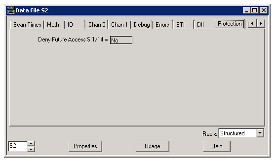
Deny Future Access S:1/14
You can allow or deny future access to a processor file. Set this bit to deny access. This indicates that a programming device must have a matching copy of the processor file in its memory in order to monitor the ladder program. A programming device that does not have a matching copy of the processor file is denied access.
When this bit is cleared, it indicates that any compatible programming device can access the ladder program (provided that password conditions are satisfied).
Processor Secured S:34/8
This bit indicates when the processor has been secured through RSLogix 500 version 7.10 or higher if you have been authenticated and authorized via RSAssetSecurity. Once you have been authenticated and authorized you will be able to go online and upload and download this processor using RSLogix 500 version 7.10 or higher. If the processor is secured the only way to unsecure it is to either disconnect the battery and clear processor memory back to factory default or install a memory module with an unsecured program configured to autoload at powerup.
(13) SLC Status, Mem Module
The status file lets you monitor how your operating system works and lets you direct how you want it to work. Depending on the type of processor you are using all of the fields explained below may not apply.
Fields on this display that are in gray are read-only. Fields shown in white are read/write. However, this information is seldom written to by the user program or programming device (unless you want to reset or clear a function). If you write to status file data, make sure that you first understand the function fully.
This information appears on the Mem Module tab with the Structured Radix selected.
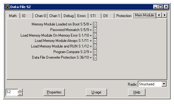
Memory Module Loaded on Boot S:5/8
When this bit is set by the processor, it indicates that a memory module program has been transferred to the processor. This bit is not cleared by the processor.
Your program can examine the state of this bit on entry into the REM Run mode to determine if the memory module content has been transferred. Word S:1/15 will be set to indicate REM Run mode entry. This information is useful when you have an application that contains retentive data and a memory module that has only bit S:1/10 set (Load Memory Module on Memory error). Use this bit to indicate that retentive data has been lost. This bit is also helpful when using bits S:1/11 (Load Memory Module Always) or S:1/12 (Load Memory Module Always and Run) to distinguish a power up REM Run mode entry from REM Program (or REM Test) mode to REM Run mode entry.
Password Mismatch S:5/9
This bit is set on REM Run mode entry, whenever loading from the memory module is specified (word 1, bits 11 or 12), the processor user program is password protected, and the memory module program does not match that password.
Use this bit to inform your application program that an auto loading memory module is installed but did not load due to a password mismatch.
Load Memory Module On Memory Error S:1/10
You can use this bit to transfer a memory module program to the processor in the event that a processor memory error is detected at power up. A memory error means the processor cannot run the program in the RAM because the program has been corrupted, as detected by a parity or checksum error. This type of error is caused by battery or capacitor drain, noise, or a power problem.
You must set S:1/10 in the status file of the program in the memory module. When a memory module is installed that has bit S:1/10 set, a processor memory error detected at power up causes the memory module program to be transferred to the processor, and the REM Run mode to be entered.
When S:1/10 is cleared in the memory module, the processor remains in a major fault condition if a memory error is detected on power up, regardless of whether or not a memory module exists.
When S:1/10 is set in the status file of the user program in RAM memory, the memory module must be installed at all times to enter REM Run or REM Test modes.
Load Memory Module Always S:1/11
When this bit is set, you can overwrite a processor program with a memory module program by cycling processor power. A programming device is not required. When this bit is set this overwriting process occurs every time you cycle power.
If you leave the memory module installed, the overwriting process, including data tables, is repeated each time you cycle power. The mode is changed to REM Run each and every power cycle.
The memory module you install in the processor must have status file bit S:1/11 set. Loading takes place if the master password and/or password in the processor and memory module match. Loading can also take place if the processor has neither a password nor a master password.
When S:1/11 is also set in the status file of the user program in RAM, the memory module must be installed at all times to enter the REM Run or REM Test modes.
Load Memory Module and RUN S:1/12
With this bit, you can overwrite a processor program with a memory module program by cycling processor power. A programming device is not required. The processor will attempt to enter the REM Run mode, regardless of what mode was in effect before cycling power.
The memory module you install in the processor must have status file bit S:1/12 set. Loading takes place if the master password and/or password in the processor and memory module match. Loading can also take place if the processor has neither a password nor a master password.
When S:1/12 is set in the status file of the user program in RAM, it does not require the presence of the memory module to enter the REM Run or REM Test mode.
Program Compare S:2/9
When this bit is set inside a valid program that is contained in a memory module, no modification of the NVRAM user program files is allowed. This includes online editing, program downloading, and clear memory commands. Use this feature to prevent a programming device from altering the NVRAM program from the program contained in the Memory Module. If a memory module is installed with this bit set, and a different NVRAM user program is contained in NVRAM, the processor will not enter the Run mode. You must transfer the memory module program to NVRAM in order to enter the Run mode.
Data File Overwrite Protection S:36/10
Use this bit to determine the validity of retentive data following a memory module transfer. This bit is always set when a memory module to processor transfer occurs with Data File Overwrite Protection selected and protected files are overwritten. Protected files are overwritten anytime a memory module program does not match to processor program at the time of the transfer. This bit is not cleared by the processor.
(14) SLC Status, Forces
The status file lets you monitor how your operating system works and lets you direct how you want it to work.
Fields on this display that are in gray are read-only. Fields shown in white are read/write. However, this information is seldom written to by the user program or programming device (unless you want to reset or clear a function). If you write to status file data, make sure that you first understand the function fully.
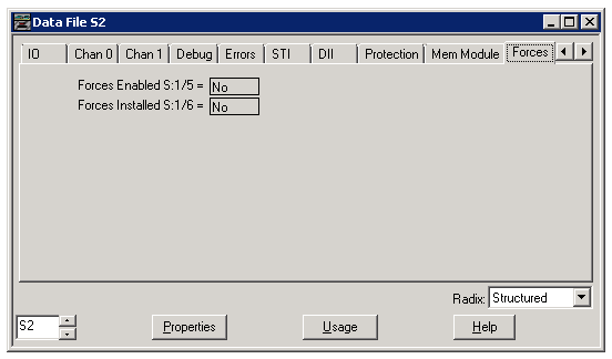
This explains the fields you see at default, or when you have selected the Structured radix to display status information. If you view status having selected any other radix see Data File dialog box.
Forces Enabled S:1/5
This bit is set by the controller to indicate that forces are always enabled. Select No to disable forces.
Forces Installed S:1/6
This bit is set by the controller (field indicates Yes) to indicate that forces have been set by the user.
Reference
- RSLogix500 Help File on SLC Status
- Introduction to Programmable Logic Controllers (Gary Dunning)